Design engineers like tight tolerances and it’s hard to blame them. Products are easier to assemble and more reliable with precise components. Unfortunately for manufacturers, holding very tight tolerances is costly and each manufacturing process has its technical limits. When a customer asks us how tight of a cast tolerance we can hold, it’s not always simple to answer. This blog series will explore the dimensional capability of high pressure die casting and answer frequently asked questions.
- How tight of a tolerance can you hold?
- Should the casting feature be machined or be controlled, “as cast?”
- How can the design engineer and the die caster collaborate to improve dimensional capability?
How tight of a tolerance can you hold in die casting?
The first question the designer should ask is, “how tight of a tolerance do I really need?” This is imperative because almost any level of precision can be achieved, however, as tolerance shrinks, the cost increases. The tolerance the designer places on the print will significantly impact the cost of the part. Therefore, this question should be seriously considered before requesting quotes.
The designer should allow as much tolerance as possible without affecting fit, form or function.
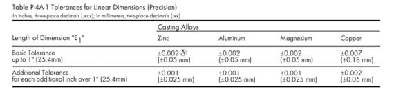
The North American Die Casting Association Product Specifications Standards for Die Casting should be a resource on every designer’s bookshelf. It is the most comprehensive book on high pressure die casting capability available. In this book, NADCA categorizes tolerances into two groups; standard and precision.
Standard tolerances are those that can be achieved using good manufacturing practices with normal levels of inspection, die life and die maintenance.
Precision tolerances are what can be achieved using rigorous tooling development and a diligent focus on process control. Holding precision tolerances during production will impact scrap rate, cycle time, inspection time, die life and die maintenance cost. Precision tolerances can be achieved, but you will expect to pay a higher casting price and replace tooling more frequently.
The NADCA Standards book details the standard and precision tolerances for dimensional characteristics that are unique for high pressure die castings. It is important to understand these concepts before designing a die cast part.
The following fictitious casting design illustrates each of these dimensional characteristics.
Example 383 alloy Die Casting
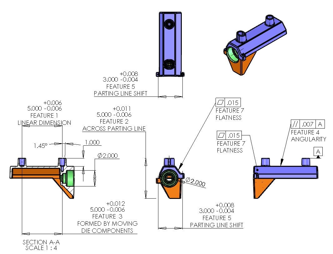
Linear dimensions
Linear tolerances are for features formed in the same half of the die. This tolerance is used to compensate for growth, shrinkage or minor imperfections during solidification.
The NADCA precision tolerance for a linear dimension allows for .002” for the first inch and then .001” for each additional inch.
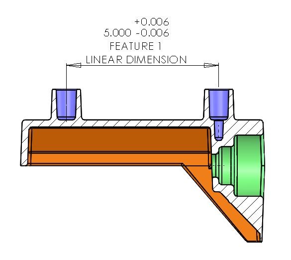
Example
This 5” feature from the center of each boss die would have a Precision tolerance of +/- .006”
Dimensions across parting lines
The die halves will separate a small amount during the injection of metal. The amount of die separation is a function of the projected area of the casting combined with the metal pressure.
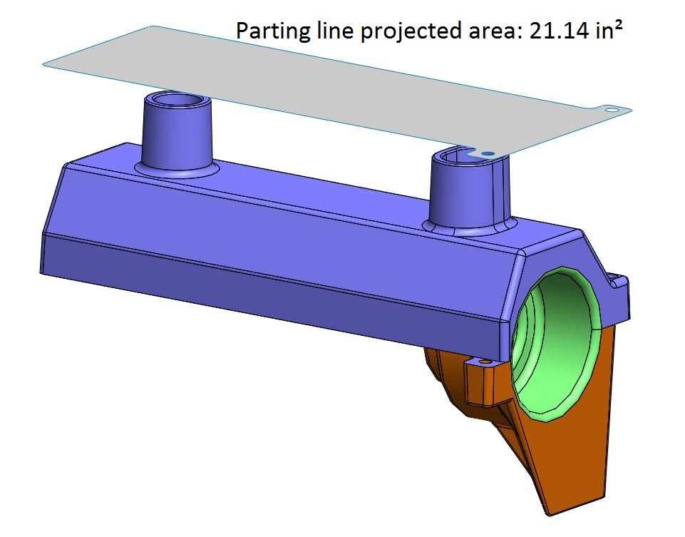
When determining the tolerance for a cross parting line dimension, you add the cross parting line tolerance to the linear tolerance.
It is only added to the high side of the tolerance because die separation will only add material to the part.
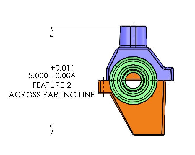
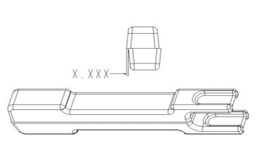
Example
This 5” feature crosses parting line and has a projected area of 21.14 square inches.
First, we determine the linear tolerance for a 5” feature, which is +/- .006”
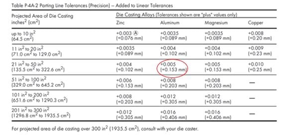
Next, we use the NADCA Specifications to determine the additional Precision cross parting line tolerance for an aluminum casting with 22.14 square inches of projected area.
The additional .005” is added to the high side which results in a tolerance of -.006”/+.011”
Dimensions formed by moving die components
Moving die components (slides) require additional tolerance to account for shift as pressure is applied during casting. The amount of tolerance is a function of the projected area of the portion of the slide facing the molten metal.
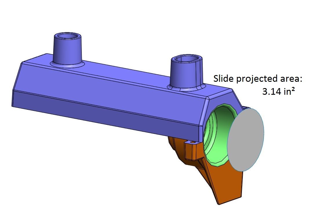
Slide movement will only add material. Additional tolerance is added to the linear dimension to compensate for the moving die component. The additional tolerance is calculated using the length of the moving component, not the entire linear dimension.
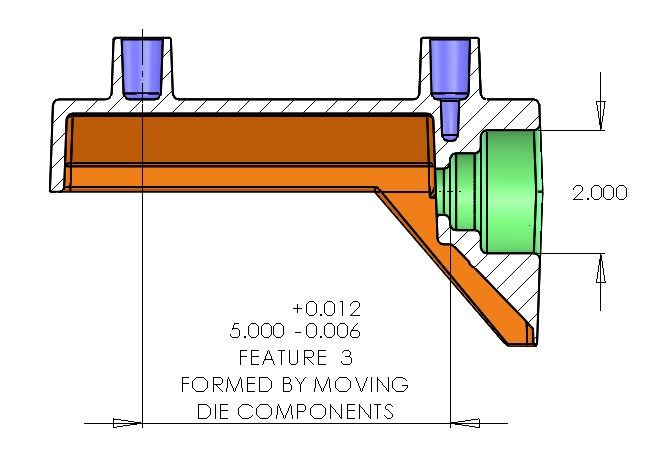
Example
A 2” diameter round slide core will have a projected area of 3.14 square inches.
First, we determine the linear tolerance for a 5” feature, which is +/- .006”
Then we consult the NADCA Specifications for the additional Precision Tolerance for an aluminum casting with 3.14 square inches of moving die component projected area.
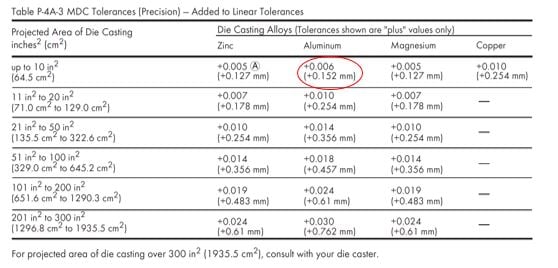
We add the .006” to the high side which results in a tolerance of -.006”/+.012”.
Angularity
Angularity refers to the angular difference between the part design and the casting. Angularity features are strongly affected by:
- The rigidity of the parts design
- The thermal balance of the die
- The size and condition of the casting machine
- Handling of the part.
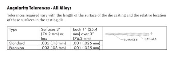
Angularity includes flatness, parallelism, perpendicularity. The NADCA guidelines defines angularity tolerances for features in the same die half, across parting line and with moving slide components.
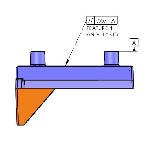
Example
The Precision Tolerance for the parallelism of two surfaces in the same half of the die is determined by taking the larger of the two surfaces and applying the NADCA tolerance of .003” for the first inch and .001” for each additional inch.
The 7” long surface will be within .007” of Datum A in the same half of the die.
Parting Line shift
A certain amount of parting line shift will occur as the casting machine closes the die halves.
Misalignment can be caused by:
- Thermal differences in the die halves
- Die cast machine wear
- Die wear
Die alignment systems, such as interlocks and guide pins, are utilized to minimize this effect.
Parting line shift is important to consider when designing and tolerancing a casting. Datum structures should be designed with all datum features in the same half of the die.
The NADCA Parting Line Shift tolerance is added to the linear tolerance to calculate the overall tolerance for that feature. The parting line shift tolerance is determined using the projected area of the casting.
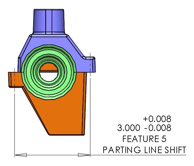
Example
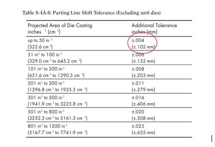
A part with 21.14 square inches of projected area will have an additional tolerance of +/- .004” added to the linear tolerance.
The tolerance for this 3” feature is +/- .008”.
Draft
All casting features perpendicular to the parting line require taper (draft) to release from the die. NADCA recommends twice as much draft for inside walls and surfaces compared to outside wallsbecause the casting will shrink on to inside walls as it solidifies.
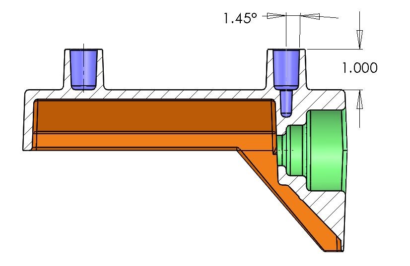
Example
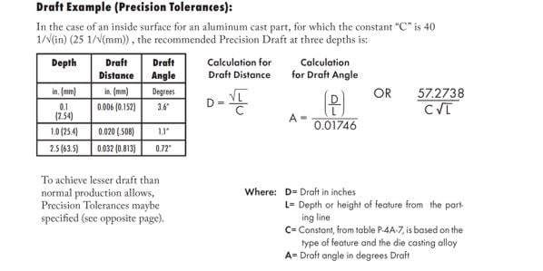
C=40
L=1
57.2738/ (40*√ (1))
Draft = 1.43°
A 1” deep feature on an inside wall should have at least 1.43 Degrees of draft to release from the die.
Flatness
Flatness is the amount of variation on a surface. You will expect to see a certain amount of variation on die castings due to solidification and distortion during ejection. Casting design plays a significant role in flatness capability. Check out our blog “10 Concepts for Successful Die Casting Design” for our recommendations for die cast design.
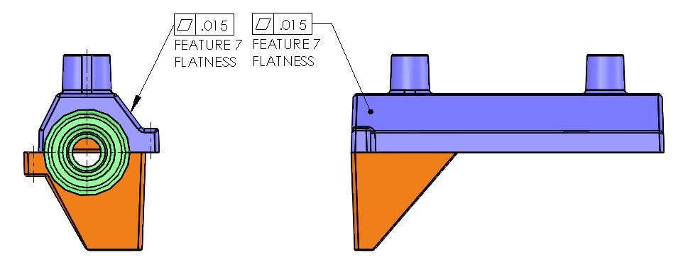
Example
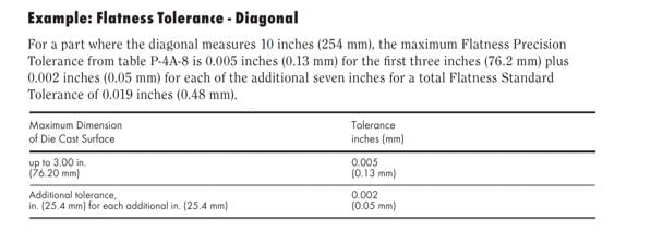
The NADCA tolerance for flatness is .005” for the first 3 inches and .002” for each additional inch. A part with an 8” flat diagonal feature will have a Precision tolerance of .015”.
Conclusion
NADCA guidelines allow the designer to determine if die casting is capable of meeting their requirements. If tighter tolerance are required then the designer and caster must decide if a secondary machining operation should be added or if its possible to hold a tighter tolerance as cast.
You can purchase the NADCA Product Specification Standards for more detailed information on standard and precision tolerances for various features. At General Die Casters, we provide or customers with a complimentary copy. This allows us to collaborate with our customers and achieve world class results in dimensional repeatability
Our next article will examine the question, “Should I machine a critical feature or control it “as cast?”